Table of Contents
Information about the KUKA lightweight robot
Here we collect some bits and pieces about the KUKA lightweight robot. We hope it is useful for someone.
3D Model of the lightweight arm

This is a blender model of the lightweight arm using subdivision surfaces. The number of vertices/faces can still be adjusted when generating meshes. It is licensed under CC-BY-3.0.
Mounting adaptors

We got some really nice adapters for the hands. Here are the original Solidworks files, some VRML meshes, a blueprint drawing and the mass / inertia properties.
FRI - the Fast Research Interface for the KUKA lightweight robot
The 19“ KUKA control box, which is shipped with most KUKA lightweight robot arms runs actually two operating systems: A Windows XP embedded which runs the GUI and a VxWorks which runs as a Windows driver and does the realtime control part.
With the FRI component, you have an extra Intel Ethernet card which is “taken over” by the VxWorks kernel. So now there are two network cards: The embedded network card which we use for a SMB share and the realtime Intel card which we use for realtime control. To this network card we connect our “remote control computer”.
FRI - YARP / ROS bridge
This is the (now outdated) program that we use in our lab to connect the lightweight robot to YARP. The program fri-yarp runs one of our PC's which is connected to the realtime ethernet card of the KUKA control box. The program FRI_CONTROL.SRC is written in KRL and runs on the robot controller in automatic mode. You need to adjust the lines that say “CHANGEME” before using it.
The program starts a high-priority thread for which it needs sudo permissions (Or some special POSIX permissions). It runs okayish on a stock Debian kernel, but a custom kernel which was compiled with realtime in mind is definitely better.
We have refactored this program to be a YARP/ROS multiclient, which also publishes diagnostics and joint states to ROS. This program is in the kuka_fri package inside the public TUM-ROS repository which can be checked out with:
svn co https://svn.code.sf.net/p/tum-ros-pkg/code tum-ros-pkg
In addition, the program communicates with the robot controller to switch between monitor mode and command mode (this needs a special KRL program running on the robot - see below). This KRL program is also stored in the above repository.
The package kuka_fri requires the package kuka_fri_header, which merely consists of the FRI header file that came on your FRI CD (probably fri_remotesample/fri_remote/fricomm.h) and a manifest.xml file:
<package>
  <description brief="kuka_fri_header">
    This is the header file for the Fast Research Interface (FRI) for
    the KUKA lightweight robot. It is shipped with the interface
    binaries for the KUKA control box.

    Please do not distribute this file!
  </description>
  <author>KUKA Roboter GmbH</author>
  <license>Proprietary</license>
  <review status="unreviewed" notes=""/>
  <export>
    <cpp cflags="-I${prefix}"/>
  </export>
</package>
We are asked not to distribute this header file so this package is unfortunately not public.
KRL programming tricks
The following bits and pieces were collected while writing a suitable KRL program for using our lightweight arms with FRI. All these programs are executed on the Kuka control box. This is our main KRL program and this is the background program that runs in the so-called submit interpreter.
FRI and KRL Movements
FRI is a low-level interface that lets you monitor and take control over the robot at a frequency of up to 1kHz. It runs completely in parallel to the KRL programs. This has a few implications:
- The KRL program maintains it's own commanded position of the arm. When in command mode, FRI adds an “offset” to this KRL-commanded position. This offset is visible for KRL programs (i.e.
$POS_ACTand$AXIS_ACTchanges). - When switching back to monitor mode, KRL tries to go back to the KRL-commanded-position - usually, where it was at the beginning of the program. This can lead to dangerous movements!
- If the switch back to monitor mode is due to an error message, then this movement happens before the program continues with the next instruction.
One way to avoid this situation is to constantly adapt the KRL position to the actual position while FRI is in command mode. Another way is to reset the program if a dangerous movement would occur otherwise.
Sending Commands from FRI to KRL
There are a few things that cannot be accomplished using only FRI:
- Change control strategy (position, joint impedance, cartesian impedance, …)
- Switch between Monitor and Command mode
- Change control rate
- Set a tool (load data)
For this kind of commands there are some general purpose fields, both in the FRI measurement and command packets:
krl.realData[], krl.intData[] and krl.boolData which are mapped to the KRL variables
$KRL_*_REAL[], $KRL_*_INT[] and $KRL_*_BOOL[]. The * can be either FRM or TO depending on
whether the variables are sent to the controlling PC or were received from it.
For catching such a command in a KRL program there are several possibilities:
- setting an interrupt on a rising edge of a flag in
$KRL_FRM_BOOL[]. - waiting for a rising edge in one of the the FRI flags:
WAIT FOR $FRI_FRM_BOOL[…] - doing busy waiting on one of the FRI variables.
We used interrupts before but when we leave command mode, we must set the KRL pose to the current pose. This cannot be done in an interrupt program: An interrupt program must return the robot to the same position where it was when the interrupt started. That's why we use the wait strategy.
This type of command sending is asynchronous, so it might be a good idea if:
- The KRL program sets a “busy” flag, as long as it is processing a command.
- The remote PC does not send any new command while KRL is busy.
- The busy flag is set for at least one cycle, so it can serve as a confirmation.
An extended version of this handshake could be a running command ID, which is sent by the remote PC and mirrored by KRL as long as the command is being processed.
Two hours time limit
After two hours of no KRL command, the robot stops the motors and hits the brakes. So, every 30 minutes we command the robot to it's current position. (It effectively does nothing). The only problem: When the robot is pushed to a limit in that moment, then the robot stops: It is over the soft joint limits and tries to set KRL to go to that pose. So this pose must be checked against joint limits and corrected if necessary. The following KRL function does this:
DEFFCT E6AXIS CLAMP_AXES(ax:IN)
E6AXIS ax
DECL E6AXIS an

an.A1 = CLAMP(ax.A1, -169., 169.)
an.A2 = CLAMP(ax.A2,  -29., 209.)
an.E1 = CLAMP(ax.E1, -169., 169.)
an.A3 = CLAMP(ax.A3, -119., 119.)
an.A4 = CLAMP(ax.A4, -169., 169.)
an.A5 = CLAMP(ax.A5, -119., 119.)
an.A6 = CLAMP(ax.A6, -169., 169.)

RETURN an
ENDFCT


DEFFCT REAL CLAMP(v:IN, minval:IN, maxval:IN)
REAL v, minval, maxval
DECL REAL r

r = v

IF v > maxval THEN
  r = maxval
ENDIF

IF v < minval THEN
    r = minval
ENDIF

RETURN r
ENDFCT
Setting load data
We usually have a 2kg hand attached to our arms. We have made a tool with appropriate load data which we can set in several ways:
- Using the menu:
Configure --> 6 Set tool/base - In a program, using
BAS(#TOOL,{tool number})After this line, the arm “behaved” but the message “480 LR Validate Loaddata FT 6” did not go away and FRISTART stopped the robot later.
- By editing the config file
/R1/Mada/$robocor.datand changing the variables$DEF_L_Mfor the mass in kg and$DEF_L_CMfor the center of gravity in mm and degrees. With this method, the robot boots with the suitable load data.
Getting Automatic external running
We recently tried to reduce the amount of button presses that are necessary to run the robot. Using the mode “automatic external”, which was meant to give a PLC control over the robot, it is almost possible to automate the teach pendant interactions.
A PLC uses digital I/O lines to send a program number to the Kuka control box, enable motors, confirm messages and start the program.
Some I/O lines can be set to $IN[1025] which is “hardwired” to TRUE. Three
other lines must be pulsed:
$DRIVES_ON: Switch on motors$CONF_MESS: Confirm messages$EXT_START: Start the program
The LWR has a limitation here: Switching on the motors by an external signal requires extra wiring (please ask your contact at KUKA for more information). The best thing one can achieve without this wiring is to have one press of the ON button when starting or re-starting after an error.
To achieve this, we loop back some output lines to some input lines, so the Kuka control box can control “itself”. Then we simulate a simple PLC inside the background program SPS.SUB.
Wiring back I/O lines
There used to be a capability called IOSIM to simulate inputs and outputs. This has been
disabled
in newer version of the Kuka control software. A second option is an I/O driver called “O2I”.
To enable this driver, do the following changes in C:\KRC\ROBOTER\INIT\iosys.ini:
- To Section [DRIVERS] add the line:
O2I=31,o2iInit,o2i_drv.o
- In Section [O2I] uncomment the two lines:
INW6=2       ;$IN[49-64]
OUTW6=2      ;$OUT[49-64]
These changes require a restart.
Update: As of KRC 5.3.2 build 28, the O2I driver got removed. However, the old driver still seems to work in the new version.
Configuring Automatic external
As expert user do
“Monitor” → “0 I/O” → “3 Automatic external”.
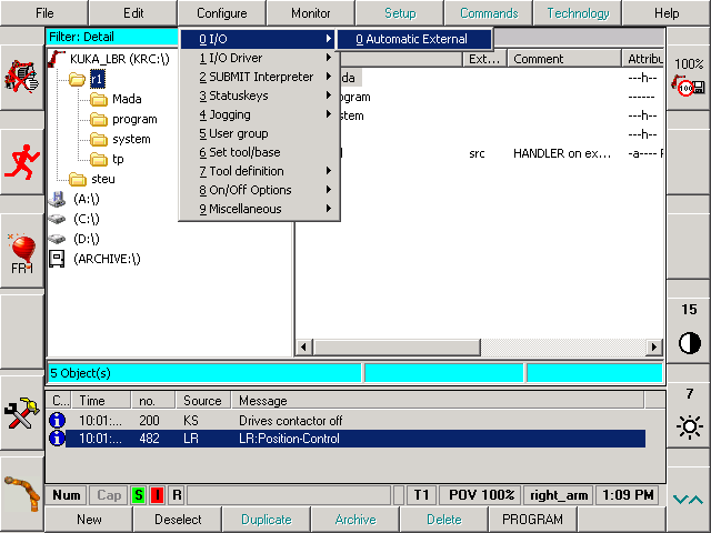
You should see the default port mappings:
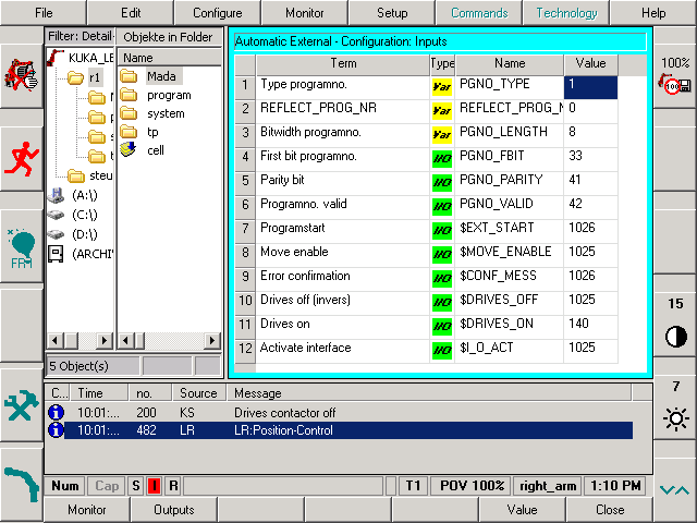
Do the following mappings:
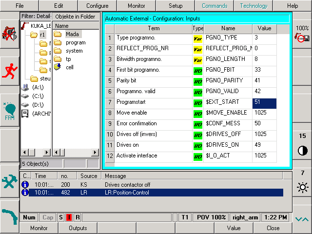
$DRIVES_ON -> 49
$CONF_MESS -> 50
$EXT_START -> 51
These mappings are stored in KRC\steu\Mada\$machine.dat.
These inputs need to get pulsed by the submit program. Also, set
$MOVE_ENABLED -> 1025
For the last change to work, set $CHCK_MOVENA to FALSE in
C:\KRC\Roboter\KRC\Steu\MaDa\OPTION.DAT.
Writing a suitable SPS.SUB
This is our version of the SPS.SUB background program.
SPS.SUB is run in the background by the “Submit Interpreter”. It is run
in parallel to the main program. Some restrictions apply and certain variables
are write protected. These are some bits and pieces that may be useful.
SPS.SUB is responsible for starting CELL.SRC when in automatic external mode; CELL.SRC,
in turn, reads the I/O lines and calls the correct program. However, with some
modifications, CELL.SRC is no longer needed. We can start our FRI control program directly.
Confirming Messages: This is a snippet for confirming messages:
INT M
DECL STOPMESS MLD
IF $STOPMESS AND $EXT THEN      ;If there is a stop message in auto external mode
   M=MBX_REC($STOPMB_ID,MLD)    ;Read current state in MLD
   IF M==0 THEN                 ;Check if we are allowed to confirm
      IF ((MLD.GRO==2) AND (MLD.STATE==1)) THEN
         CONFIRM MLD.CONFNO     ;Confirm this message
       ENDIF
   ENDIF
ENDIF
When omitting the check MLD.STATE==1 then almost every message gets confirmed.
In this application this makes sense after the ON button was pressed.
Controlling the program state: By writing commands to the $CMD stream one can start, stop or reset
KRL programs:
CWRITE($CMD,STAT,MODE,"RUN /R1/FRI_CONTROL()")
CWRITE($CMD,STAT,MODE,"STOP 1")
CWRITE($CMD,STAT,MODE,"RESET 1")
Some variables:
$MODE_OP: One of#EX,#AUT,#T1,#T2. The current robot mode.$EXT: robot mode is “Automatic external”. This is a bit more compact than($MODE_OP==#EX). Similar variables are$T1,$T2and$AUT.$PRO_STATE1:#P_RESET: The program was reset#P_FREE: No program selected#P_ACTIVE: Program is running#P_STOP: Program is stopped
$PERI_RDY: Drives are ready$STOPMESS: A stop message is being displayed$PRO_ACT: A program is running
The following variable is not supported with FRI 1.0.0, but has been used by others:
$FRISTATE: Can be#MONor#CMD
IO-lines on the Kuka-C2 controllers
The KRC that ships with the lightweight arms has no physical input or output lines. You have to attach some IO-module using an industrial bus. However, there is a (pretty hackish) way to get some slow IO-lines with only a few wires and some code:
From KRL it is possible to control the serial port COM3 and send (and receive) some command characters (using the CWRITE and CREAD commands). Then you connect COM3 to COM2 (which is controlled by the windows side) These commands are interpreted by a windows program which runs on the KRC in the background (find the source here). This program can set the handshake pins on the serial port or control the parallel port. See the wiring diagram below:
             ______________________
         ___/________________      \
       _/___|________________\_    |
      / |   |                | \   |
      | |   |                | |   |
      | |  _|_____           | |   |
   RxD| | / |     \       RxD| |   |
     TxD| | +---\ |         TxD|   |GND
  ____|_|_|_|__ | |      ____|_|___|__
  \ 1 2 3 4 5 / | |      \ 1 2 3 4 5 /
   \ 6 7 8 9 /  | |       \ 6 7 8 9 /
    ---------   | |        ---------
       COM2     | |          COM3
                | |
             GND| |DTR
                | |

               OUTPUT
The serial port should provide two outputs and two inputs (+-12V). The parallel port has some more…
Other things to know
- The second joint (J2/A2) is at 90 degrees when it is completely stretched. This is due to some convention of Kuka. However, the FRI interface does not have this offset. With FRI, all joint limits are symmetric (i.e. J2 is zero when stretched). This suits us well, we would have removed this offset in our driver, anyway.
- When the variance of the estimated force (
$TORQUE_TCP_EST) is bigger than around 10-15, then the arm is in a singular pose and the estimated forces should not be trusted. - The message “483 - LR - Computation of Cartesian Deviation impossible” can be overcome by switching back to position control. This requirement is reportedly gone in the newest version of FRI.
Glossary
- KCP: KUKA control panel
- KRC: KUKA robot controller (control box)
- KRL: KUKA robot language
- RSI: remote sensor interface (older)
- FRI: fast research interface (newer)
- RDW: resolver-digital-wandler